|
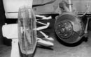
I 'm not sure how it got started, calling a single chamber '65-6G Mustang master cylinder a fruit jar. I think it was because the lid is large and screws on like one. This is a good safety point we should all know about. And, as street rodders, we should try to encourage others who still use any single chamber master to replace it! If you loose brakes in the front or rear with a fruit jar, you've lost all braking capability. With a dual chamber master, the rear line coming out of the master cylinder (next to the pushrod—the larger reservoir) goes to the front wheels (usually discs), while the front line (farthest from pushrod—the smaller reservoir) goes to the rear wheels (usually drum). Now, if one of the lines or hoses breaks, you'll still have front or rear brakes to stop the car. Late-model cars have gone one step further, using a four-port master cylinder. Two ports from each chamber (one with a residual check valve for rear drums) helps split the brake system diagonally. One front brake and one rear brake are fed by each chamber (check illustration). Now, if you loose any one wheel, you'll still have a front and rear wheel that will keep the car relatively straight as you stop.
If you're replacing the Mustang fruit jar, which has an integral brake light switch, (the threaded hole in the casting is for the switch), you'll need to add a brake light switch, T'd into either front or rear lines coming out of the master cylinder. At the parts house, you can ask for a hydraulically actuated, electronic stop light switch (Borg/Warner # S-194). Or, your old '6566 Mustang brake light switch can be used in this T, if it's in good working order. Installation can be accomplished with a three-way T (Everco # 652-B) that has l/8 inch pipe threads on top (for the switch), and 3/8-24 thread for 3/16-inch brake lines on each end.
You'll also need to separate the front and rear lines where they are T'd together under the chassis. This means you'll need to buy another length of 3/lG-inch brake line with ends, to go from the T to the master cylinder. I here are now two different sizes on the dual-chamber master. If you don't have a double flaring tool to attach the correct ends on the new brake lines, here's your option. Once at the master cylinder outlets, you will notice you need an adapter in the 1/2-20 front wheel port (nearest the pushrod hole). The Everco part # 7817 adapts from l/2-20 to 1s-24 for 3/16-inch brake line, while Everco # 7818 adapts 7/16-24 to 3/8-24 for the rear wheel brake line port fitting on the master (farthest from the pushrod hole). All aftermarket, 3/16-inch- diameter brake line has 3/8-24 fittings on the ends.
I had no idea there were so many manual (not vacuum power-assisted) replacements for the fruit jar! There may be more. The distance between the two mounting holes in the fruit jar and the dual-chamber master cylinder is 3.2 inches, or a hair under 3 13/64 inches. The manual master has a deep pushrod hole, while the power-assisted master cylinder has what appears to be just a shallow countersink hole. T he deep pushrod hole will afford less chance of the pushrod falling out of it, should something happen. All the dual--chamber masters listed have a 7/8-inch diameter bore (the '65 Mustang fruit jar has a one-inch bore), with the exception of the aluminum master cylinder, which has a 21mm bore. This is about 2mm smaller than a 7/8-inch bore. The aluminum master has been internally anodized to minimize corrosion, just like all 'Vette calipers. You may be asking yourself; what happens when I go from a one-inch bore to a 7/8 inch bore? This will up the line pressure, giving a higher, firmer pedal. You won t have to apply as much pressure to stop the car, and will also have the option of right or left exit ports from the master cylinder (which- you should be concerned with if your master is mounted backwards under the floor) depending on your pedal arrangement (swinging pedals or under-floor pedals). The reference point for right or left exit lines is with the pushrod port facing the viewer.
Before '68 the residual check valve was in the master cylinder bore. A Federal safety law enacted in 1968 placed the residual check valves at the exit ports, just behind the brass inverted flare, where they are easily removed with a sheet metal screw. In fact, some are threaded, and some kits include a screw if you are using the master on a disc/disc system (remove both). The internal components in the masters listed are the same, and can be used for both applications by simply removing the residual check valve for the disc end of your car (or both valves for disc/disc applications), leaving the check valves if you have four-wheel drum brakes. How do you check for residual check valves? Easily—just remove the inverted seat and you can see at the exit port with a small screw. Behind the inverted flare is a black rubber "duck bill" (with a round base) that goes up into the back of it. This is the residual check valve, held M the back of the inverted flare with a small spring. Remove the spring and "duck bill" for disc brake setups, and leave it in for drum brakes. If your system is split drum/disc, only remove one. Do not forget to include the inverted flare, since this is what seats it on the brake line. The larger, rear reservoir (next to the pushrod) is always for front disc brakes (it can be used for drums), which need more volume than the master s smaller, front chamber (farthest from the pushrod). The small reservoir is for wheel cylinders, that take a lesser volume of fluid than disc pistons.
Dual Chamber replacements for the fruit jar
Note Numhers listed are parts house or brake shop: numbers, NOT Ford or GM numbers which are more expensive.
'78-81 FORD FAIRMONT Raybestos # MC 39037 (R.H.) GRANADA (cast iron) 7/8 bore FUTURA ZEPHER (Mercury)
'81-86 FORD T BIRD Raybestos # MC 39531 (R.H.)
'82-86 MUSTANG (aluminum) 21 mm bore
'83-86 MARQUIS (Mercury)
'81-83 FORD ESCORT Raybestos # MC 39310 (R.H.) EXPLORER (cast iron) 7/8 bore LYNX MARK 7 (Lincoln)
'76-80 GM Monza Raybestos # MC 39027 (L.H.) SKY HAWK (cast iron) 7/8 bore (L.H.) STARFIRE 5/16—MC 36231 (L.H.) SUNBIRD
An Over View of Brake Bleeding
PRESSURE BLEEDING
Pressure bleeding requires a pressurized (air over fluid) tank with brake fluid and a special plate with neoprene gasket that locks over the top of the master cylinder. These two items are connected by a pressurized air hose that provides about 20psi to the system. This type of system should be used by a professional only. Available at most brake shops, it simply pressurizes the entire system with brake fluid so one man can quickly bleed all four corners without having to add fluid or have help. Simply open the bleeder about ~/4 turn and allow all the air to come out, then close the valve. This is the best method to bleed just about any brake system, although there are a few exceptions.
MANUAL BLEEDING
This method is by far the least expensive, however it requires another pair of hands and a couple of cans of brake fluid. Making sure the reservoir is topped off, one person pumps up and holds the pedal, while the other opens the bleeder valve and lets the air out, then tightens it. This process is repeated on each wheel until all air is removed. This method has probably been used by just about anyone who has ever done their own brake maintenance. It is also one of the simplest ways to remove air from the system, however, this method may not be 100-percent effective on more complicated systems, such as modern four-wheel disc equipped cars.
GRAVITY BLEEDING
This can be described as the slowest, yet its also considered the least harmful way to bleed your braking system. As mentioned, air bubbles trapped in the system float to the highest point (if you have a vented cap or a bad seal at the master cylinder lid, that is). Vented caps, however, are obsolete on current production passenger cars. Diaphragms are usually found inside the lids of most master cylinders as part of the gasket, and will hold air in the line just as putting your finger over a straw full of water does. Depending on how you plumbed the system (remember, high spots will hold bubbles), you may also have to power bleed and/or manual bleed the system. For gravity bleeding, the master cylinder must be higher then the calipers or wheel cylinders. Gravity bleeding is as simple as filling the reservoir (leave the lid off) and opening the brake bleeders. Do not let the reservoir go empty, Check it periodically or you will have air in the system again. You may want to put the wheel cylinders or calipers in a pan and make sure the bleeders are pointing up.
VACUUM BLEEDING
This can be accomplished with a device, such as the Neward Enterprises' Mityvac vacuum pump that, among it's other capabilities, will bleed brakes. This vacuum pump can also be used for trouble shooting engine cylinder leak-down, fuel pumps, tank lines, distributor vacuum advance, transmission modulator vacuum problems, bench bleeding new master cylinders, brake boosters, siphoning liquids, any vacuum operated accessories, and much more. It's billed as a one man bleeder, since vacuum is drawn from each caliper or wheel cylinder at one time. Its recommended that 17-to-20 inches of vacuum be used on each caliper or wheel cylinder. This is equivalent to 10psi.
CHANGING CALIPERS AND WHEEL CYLINDERS
If you have neoprene brake hose, and are just changing wheel cylinders or calipers. a clamp can be used to keep the air from traveling up the line. Both good judgment and reasonable pressure should be used here. Use gentle pressure on the neoprene hose— just enough to stop the flow. This method should not be used on stainless braided lines, as they have Teflon inner liners that can collapse. Disc brake bleeders should always be at the top of the caliper, so you can bleed them without taking them off the bracket. If they're on the bottom, remove them from the bracket and turn the bleeder upwards before proceeding. If this is the case you'll need to place an old rotor or a piece of wood the same thickness between the pads while the bleeder is in this positron.
SILICONE VS. REGULAR FLUID
Probably two of the most likable differences about silicone (DOT 5) is the fact that it won't eat up paint if spilled, and acts as a non-corrosive lubricant for all brake parts. Regular brake fluid (DOT 3 and 4) will soften paint before you can wipe it off, and sometimes you'll wipe off the paint too! Using a spray bottle, lay a fine mist of water on the painted surfaces first, to float away any DOT 3 or DOT 4 fluid, keeping it from attacking the paint (this works, since oil and water don't mix).
FLUID TEMPERATURE RANGES
Both types of regular brake fluid (DOT 3 and 4), and silicone (DOT 5) all have different boiling points. A dry boiling point refers to the time of manufacturing. A wet boiling point refers to after the can has been opened. Moisture is absorbed as soon as the can is opened. Do not leave the Iid off, no matter what type of brake fluid you use. If you find it has been stored in this manner— don't [USE IT! All brake fluids will absorb moisture, although silicone seems to be the least affected. Regular brake fluid is designed to absorb moisture, inhibiting water pockets from forming in the system.
To give you an idea of the temperature ranges, DOT 3 has a dry boiling point of 401 degrees and a wet boiling point of 284 degrees. DOT 4 has a dry boiling point of 44G degrees and a wet boiling point of 311 degrees. And DOT 5 (Silicone) has a dry boiling point of 500 degrees and a wet boiling point of 500 degrees (because it does not absorb moisture). Bleeding bubbles from Silicone is more difficult then regular brake Fluid and can generate internal foaming, even when pressure bleeding. Silicone generally doesn't give a hard pedal like regular Fluid, and is slowly being fazed out.
MASTER CYLINDERS LOWER THAN CALIPERS
This shouldn't be a problem, however, if you experience problems you feel are due to a low reservoir, check the master cylinder lid. It shouldn't be vented, but should have a neoprene diaphragm/seal. If it has a poor seal or is vented, Fluid could drain back to the reservoir. If the cap is vented get rid of it and get a newer master that is sealed and has dual chambers. You can also have bad seals in the caliper, or wheel cylinder, that need to be replaced (air could be drawn in around the seals). There are two-pound check valves that can be placed in the line for disc brake setups, and 10-pound check valves for drum brakes, to keep Fluid from Rowing backwards in the line and loosing pedal.
CAMSHAFTS AND VACUUM
These don't always work together to benefit your brake booster. A high-lift cam can suck away a lot of vacuum from your power brake booster. You must have a vacuum check valve between the engine and canister/booster. Remedies are available, like electric vacuum pumps that come on only when necessary, and dual-diaphragm vacuum boosters. Additional volume can also be achieved by adding an extra reservoir canister. This gives more storage capacity, but will not increase the overall vacuum level. This should, however, stabilize the level of vacuum if you have other vacuum-operated accessories.
RULE OF THUMB
Your brake pedal ratio should be about five to one. We're talking about the length of the brake pedal arm here. To figure your pedal ratio you'll need to measure in a straight line from the centerline of the pivot pin to the centerline of the pedal, we'll call this value X. Then measure the distance from the centerline of the push rod to the centerline of the pivot pin. We'll call this value Y. Simply divide Y into X. Example: if X = 10 inches and Y = two inches, the answer is five inches (or five-to-one).
If you're putting a brake system together and you're not sure what diameter master cylinder bore to use, find out what the manufacturer recommends (or used) with your setup, both front and rear. This should give you a good idea on diameter. Remember, when bore size goes up line pressure goes down, and pedal travel decreases. But when bore size goes down, both line pressure and pedal travel increase.
SEASONING BRAKE LINING
This is a must! New brake lining or pads should never be driven hard right out of the box! Metallic pads should have 15 to-20 soft stops over two-or-three miles (don't come to a complete stop if you don't have to). Organic pads and shoes should have about l0 easy stops or slow-downs. If you do have to come to a complete stop, don't hold your foot on the brake. The idea is to avoid getting the new pads or lining hot. If you feel you did get them hot, let them cool completely.
SAFETY
Safety, in this case, means having your brake system function correctly! If you don't know, or aren't sure about bleeding, or installation of new parts, call one of the sources listed at the end of this article. Please seek professional help if you have any doubts at all—it could mean saving a lot of bodywork, even rebuilding the backside of your garage!
|
|