|
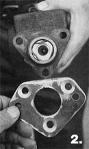
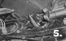
4. The side of the adapter (away from the viewer) attaches to the stock pedal bracket on the frame. This is why the adapter has countersunk holes on the master cylinder side.
5. The adapter picks up the three hole pattern on the bracket for attachment. The stock pushrod is used with this kit. Master cylinders with different bore diameters are available for your disc/drum or drum/drum situation. Notice the square inspection door in the floor. This hole may have to be enlarged to accommodate the longer, taller, dual-chamber master cylinder lid.
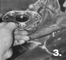
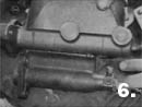
6. The two ports in the upper master cylinder still have the plastic plugs in the holes, but you'll see there isn't much distance to make up with new line between the two different outlet ports on the two master cylinders. Depending on how your car is plumbed and the type of system, your old lines may be long enough, requiring only an adapter and/or residual check valves. On the lower master cylinder (just under his lower finger), is the brake light switch coming out of the end of the old master cylinder. The kit provides a new switch and in-line "T," since you'll need to mount the switch in-line.
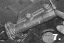
7. In the upper right hand corner, you'll notice the old lines. One of the lines will usually connect, while the other will need to have the six-inch extension (provided in the kit) and brake-light switch added. The larger chamber in the master cylinder goes to the disc brakes.
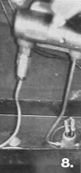
8. It doesn't matter which line you install the brake light switch in, since both front and rear work at the same time. In this installation, the switch is in the line to the front disc brakes, while a residual check valve has been installed in the rear (drum) line at the master cylinder. The residual check valve keeps the wheel cylinder (via the return springs on the shoes) from retracting all the way back in every time you let off the brake. Notice (inside the frame rail) how the new brake-light switch has been plumbed into the line using the "T."
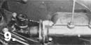
9. The stock brake and clutch pedals used a common shaft. Noticed the shaft has been shortened and the clutch pedal has been removed, leaving the uncut bracket and stock brake pedal and pushrod. With everything totally installed, it makes a clean, simple, easy-to-install setup for disc/disc, disc/drum, or drum/drum.
|